Introduction
Fans can be selected by different methods.
- In the planning stage a quick overview is achieved using the quick selection tables (axial, radial) combined with the overview charts in the chapters "Axial Flow Fans" and "Centrifugal Fans".
- The Witt & Sohn fan selection programme offers a more detailed selection. To use the program and to receive regular updates, a free registration is necessary.
- We are happy to prepare an individual offer for you.
Fan curves
All fan curves relate to single stage fans. The standard fan curves are measured on a standard test chamber acc. to ISO 5801 with free inlet and outlet. All data refer to standard air density = 1.2 kg/m3. All jet fans were measured on a standard test stand according to ISO 13350.
Disturbed inlet and/or outlet lead to pressure losses and volume flow rate reductions, which have to be taken into account when specifying the fan data.
Installation resistance curve
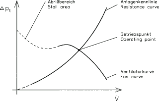
Every installation has a characteristic resistance curve, which often resembles a parabola with a more or less pronounced displacement.
Operating point
The intersection between the resistance curve and the fan curve is the operating point (also called working point). When selecting the fan, one tries to put the operating point close to the point at highest efficiency of the fan curve in order to minimise power consumption and noise generation.
For axial flow fans and some other type of fans it is furthermore important to ensure that the fan never will operate in it's stall area.

Shaft power
The fan shaft power is calculated as follows:
$ P_{w}= \frac {\dot{V}[m^{3}/h] \cdot \Delta p_t[Pa]} {3600[s/h] \cdot \eta [1] \cdot 1000[w/kW]} \; in \; kW $
Where
- $ \dot{V} $ is the volume flow rate in $ m^{3}/h $
- $ \Delta p_t $ is the total pressure increase in $ Pa $
- $ \eta $ is the fan efficiency
in the operating point.
Motor reserve
The resistance curve is often not well known. It may, due to air density variations, be subject to large variations. If no special conditions prevail a rough guideline is to have a motor reserve of 10 − 15 % for axial fans and 10 to 25 % for radial fans.
Tip speeds
Most of our impellers have been optimised using finite element simulations. Depending on the impeller material used the fan tip speed is the main limiting factor for the maximum permissible fan speed. The appendix to the computer fan selection programme describes the maximum tip speed limits for normal applications. If higher values are needed, please inquire. With technical changes and different material selection higher values can be achieved.
Total pressure increase over the fan Installation type acc. to ISO 5801

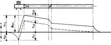
A) Free inlet, ducted outlet.
Total pressure increase:
$ \Delta p_t = p_{s2} + p_{d2} $

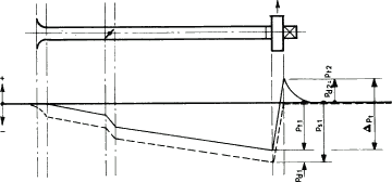
B) Free outlet, ducted inlet.
Total pressure increase:
$ \Delta p_t = p_{d2} + p_{d1} - p_{s1} $
When the inlet area is equal to the outlet area, then
$ \Delta p_t = -p_{s1} $

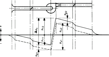
C) Ducted inlet and outlet.
Total pressure increase:
$ \Delta p_t = p_{s2} - p_{s1} + (p_{d2} - p_{d1}) \\ = \Delta p_s + (p_{d2} - p_{d1}) $
When the inlet area is equal to the outlet area, the total pressure increase Δpt is equal to the static pressure increase Δps. If the suction area is equal to the discharge area, the total pressure increase is Δpt equal to the static pressure increase Δps because pd1 equals pd2.
Our fan selection
The use of the various fan selection methods by the client should only be employed for preselection. For the final selection the necessary data acc. to DIN 24 166 should be given to one of our sales engineers to select the most appropriate fan for the desired application.
Data Sheets
To avoid want of clearness we have developed general axial and centrifugal data sheets, with which the complete delivery scope can be specified. We ask the customers to carefully check whether the fans offered are satisfactory in all aspect and if in doubt ask for clarification.

