Centrifugal fans
Production description
A large selection of outlet positions, casing geometries, casing thicknesses and materials is available for the various fan types. The following is a description of the standard product range. A very flexible production allows special requirements to be met as well.
| Category | Description |
|---|---|
| Inlet size | 63 bis 2500 mm |
| Casing thickness | 1,5 bis 20 mm |
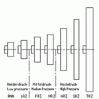
| Casing types | RNZ (Low pressure) LRZ (Low pressure) PRZ (Medium pressure) MRZ (Medium pressure) HRZ (High pressure) SRZ (Ultra high pressure) TRZ (Ultra high pressure) |
| Impeller types | Minimum 6 types per casing including dust impellers |
| Motor frame size | 63 up to 450 |
| Drive type | Direct-, coupling− or belt drive |
| Material | Steel, aluminium, special alloys |
| Casing form | Short/long casing, swing out with/without shaped inlet |
| Outlet position | according to Eurovent |
| Special design | Flame-proof, extreme temperature, gas-tight, decontaminable, corrosion resistant, earth quake safe, shock proof, according to requirements |
Standard Accessories
- Shaped inlet
- Fire damper
- Protection grill
- Mushroom cowl
- Vibration attenuator
- Jet cowl
- Flexible connection
- Counter flange
- Silencer
- Variable inlet vane
- Insulation
- Sound enclosures
- Monitoring instruments
Our centrifugal fan range has been developed to allow most combinations of volume flow rate and pressure to be realised with direct drive fans. Since the fan range is based on a modular system the majority of fans can be manufactured from standard components. This allows for short through put times and competitive prices.
The fan selection graphs make possible a quick selection of the centrifugal fans normally used at 50 Hz. They provide the fan type, the size, number of poles of the motor, the shaft power and the sound power.
The quick selection tables/nomogramme sheets and dimensions sketches give an overview of the most commonly used centrifugal fans.
In addition to the shown standard fans we also manufacture a large number of special designs, according to customer needs on a one-off basis. In case of demand for special fans please inquire.
The following is a description of our centrifugal fan programme.
Dimension sheets
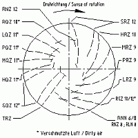
According to the new EUROVENT-Standard the installation position and thereby also the direction of rotation of the impeller for centrifugal fans defined from the drive side and not as done early from the inlet side.
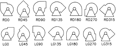
Outlet position viewed upon the drive side
Design
The design of a centrifugal fan is mainly determined by the geometrical conditions of the installation. The following gives an overview of our most common designs. In addition we manufacture a large number of special designs to customer specifications. If you need dimensions to design not in the catalogue, please inquire.
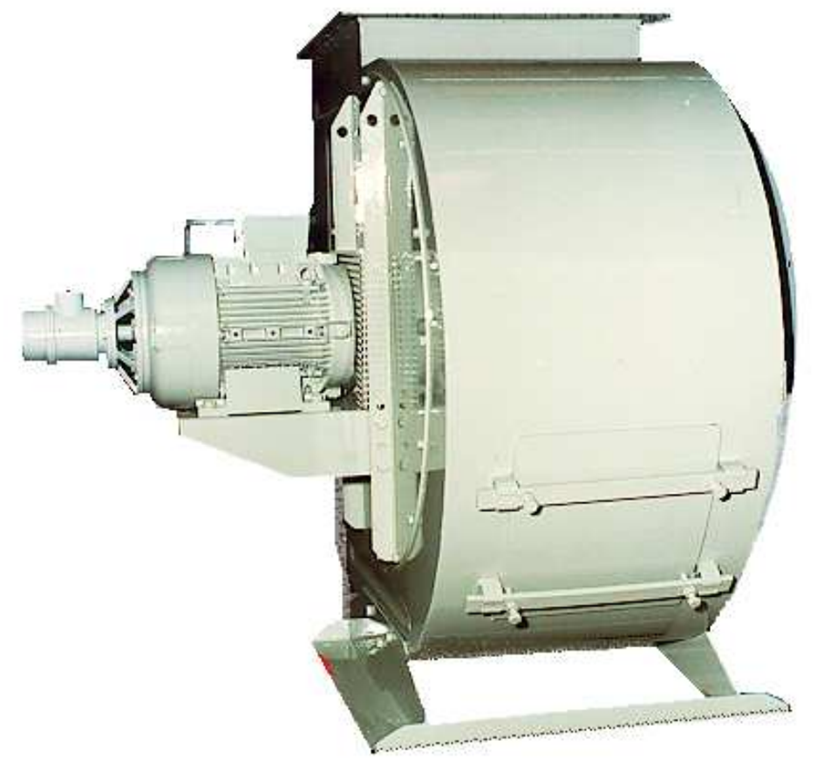
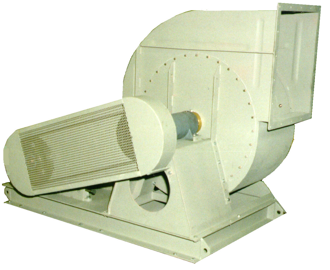
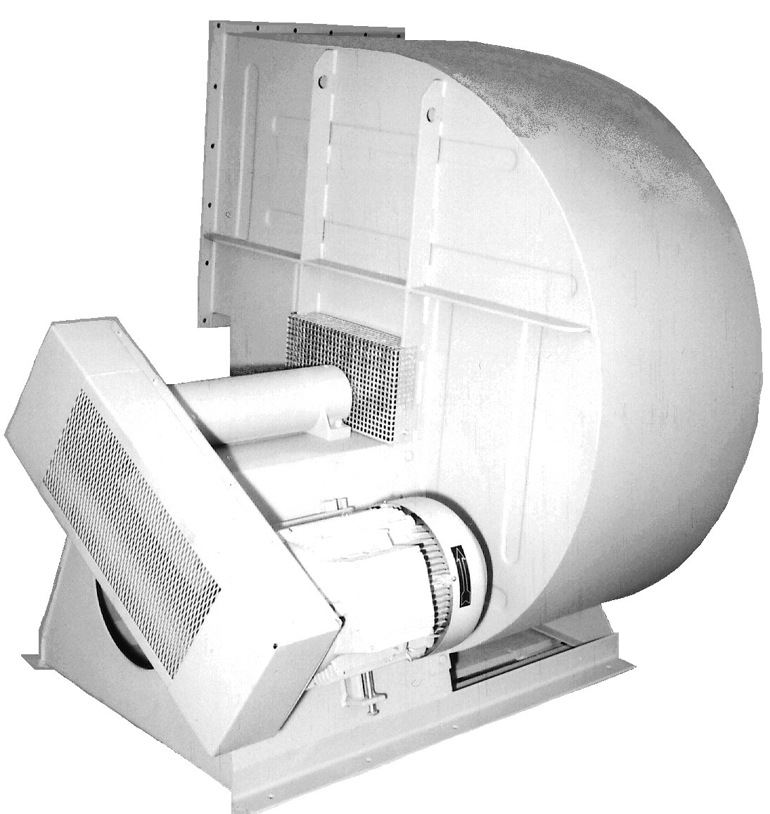
Design 1 (3d and 6d)
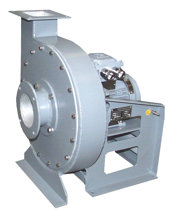
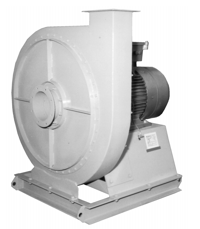
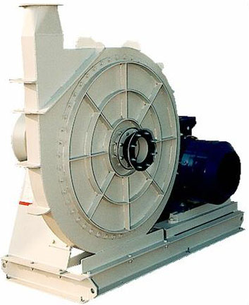
In many cases one attempts to use a direct drive. It is more compact, has less parts to be serviced and in most cases is cheaper than other designs. We offer 3 different direct drive designs. The designs 3d and 6d differ from design 1 by being turnable and that the impeller can be removed from either side. By using a flange mounted motor the design 6d is light and compact.
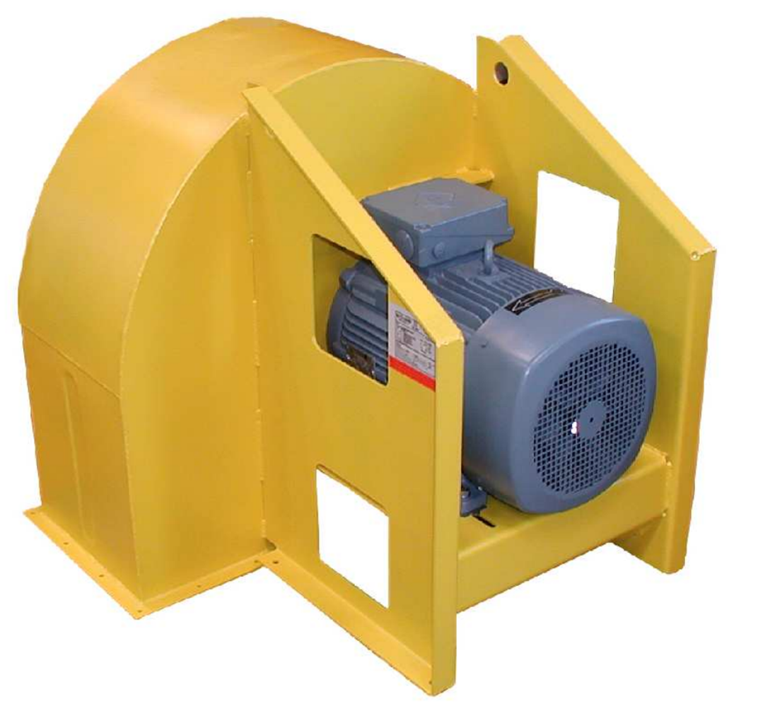
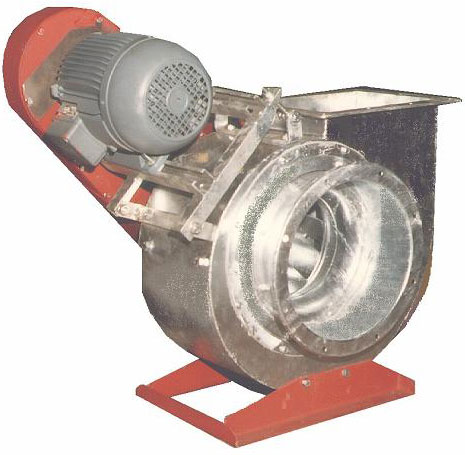
Design 2/2a, 2b, 2c
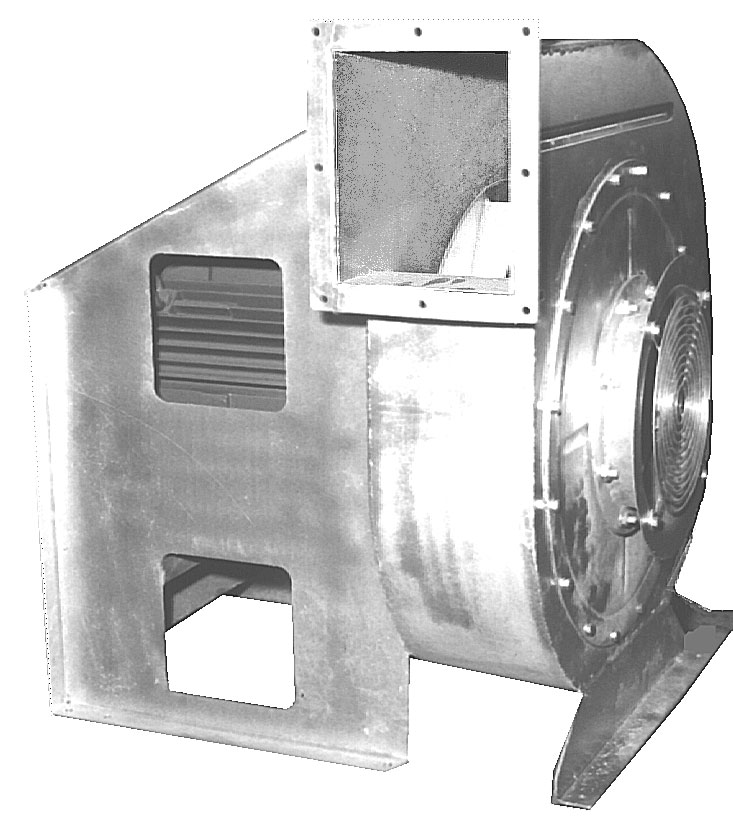
When fan speeds that cannot be achieved with direct drives or there are installation specific requirements, a V- belt drive is used. The motor mounting can be done in a number of different ways. In the design 2 the fan and motor is mounted on a common base frame (2a is the same design with a turnable casing and an impeller that can be removed to either side). The design 2b has the motor mounted on the side of the pedestal to achieve a more compact design. In design 2c, when small motors are used, the motor is mounted inside the pedestal with an outside terminal box. Although this design is more difficult toservice it is the most compact v-belt drive and cheaper than the other V- belt drive alternatives.
Design 4
When a compact design is needed, the design 4 offers an interesting alternative. However relatively extensive reinforcements of the casing are necessary.
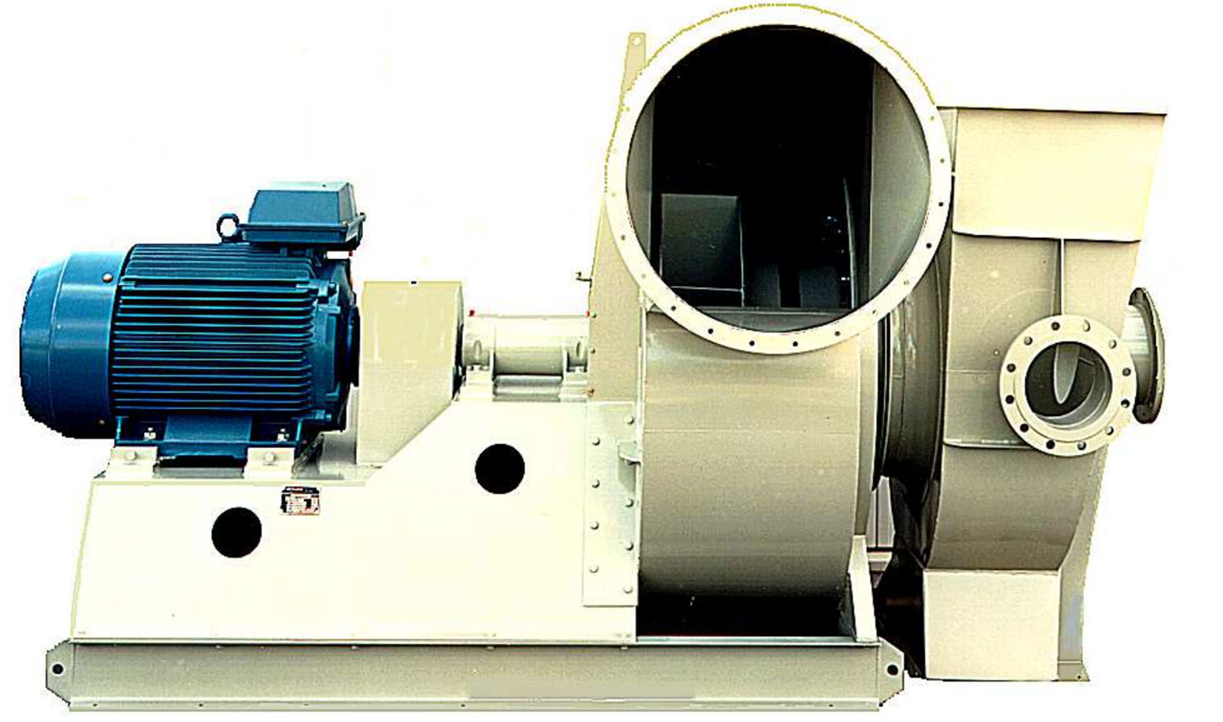
Design 5
Increasingly a drive using an elastic coupling is being used. The coupling allows starting torque or variable torque e. g. when using the fan for material transport to be dampened while protecting the motor.
Impeller program
The quick selection tabelles/nomogramme sheets give an overview of the performance of our centrifugal fans. We manufacture them as a standard in steel or aluminium. Aluminium has the advantage of being light resulting in lower inertia torque and lower starting currents.
However we have extensive experience with other materials e. g. various stainless steels. The Witt & Sohn fan range has been developed with the aim that a multitude of impellers fit into the same casing. This means that if a change of the installation is necessary this can often be achieved by replacing the impeller without having to replace the whole fan. We would like to add the following description of the various fans characteristics.
Low pressure radial fans
This is a familiy of impellers with the same external dimensions fitting into the casing type RN. The casings can be made with a cut-off (e. g. type RNZ) or without cut-off (e. g. type RNN).
A. Type RN
The most important impellers within the RNN family are:
1) Type RNZ9
This impeller type with 9 backward curved blades and pressed induction nozzles has high efficiencies, a very favourable noise behaviour and a very stable characteristic curve. The power requirement increases only slightly with increasing air volume.
2) Type RSZ10, RSZ10A, RSZ10B, RSZ12
This type resembles the previous types, but has 10 resp. 12 backward inclined, S-shaped blades with a steeper pitch. It produces higher pressures and is less susceptible to dirt with a somewhat lower efficiency. The additions A and B indicate shortened blades.
3) Type RNZ12
Due to its relativ steep blade angels it are not suited to throttling to very low volume flow rates.
4) Type VPZ
This impeller of classical scirocco design fits into the same casing. This gives the advantage of relatively high performance within a small casing. However, the efficiency is compared to the other RNN-impellers relatively low, where the shaft power depends highly on the throttling.
B. Type LRZ
The LRZ types have 9 backwards bent impellers. They consist of 4 different impellers LRZ9, LRZ9A, LRZ9B and LRZ9C. The LRZ fills the gap between the RNN types and the medium pressure fans PRZ/MRZ.
For dusty air fan we offer the impeller LQZ11. The LRZ range is very suitable for use in fuel burners since it can be throttled virtually across the full volume flow rate range.
Medium and high pressure fans
A completely new range of medium to high pressure fans with family designations of LRZ, PRZ, MRZ, HRZ and SRZ has been developed. They make it possible for us to reach every working point from low to high pressure without any gaps and uniformly high efficiencies.
Each family in turn consist of 5 to 6 impeller types. By using a modular system it has been possible to keep many of the key dimensions the same, allowing for some interchangeability. All fan casings and impellers are as a standard made in steel or aluminium. If needed we manufacture all fans in other materials as well.
Overview of impeller types Casing sizes with equal inlet diameters
A. Type PRZ
This type with 9 backward inclined blades has 4 different impellers. PRZ9, PRZ9A, PRZ9B, PRZ9C. This is a classical medium pressure fan which achieves efficiencies of up to 85 %. In this range the impeller PQZ11 can be used for material transport.
B. Type MRZ
For somewhat higher pressures in the medium pressure range the types MRZ are available. Altogether 6 impellers are available: MRZ9, MRZ9A, MRZ9B, MRZ9C, MRZ9D, MRZ9E. In addition a dust impeller is offered with the designation MQZ11.
C. Type HRZ
The high pressure fan HRZ with 10 backward inclined shaped blades achieves an efficiency of up to 81 %.
This impeller family has 7 different impellers: HRZ10, HRZ10A, HRZ10B, HRZ10C, HRZ10D, HRZ10E, HRZ10F. Also for the HRZ family we offer a dust impeller designated HQZ11.
D. Type SRZ
For ultra high pressures and small volume flow rates we have developed the types SRZ12, SRZ12A, SRZ12B, SRZ12C, SRZ12D plus the dust impeller SQZ12.
Dust fans
For each impeller family we offer a dust impeller for material transport. Their designation is RSZ, LQZ, PQZ, MQZ, HQZ and SQZ.
Other fans
Free running impellers RLN
RLN is the designation for the RNN impellers which are used without a casing e. g. for air conditioning boxes or filter boxes. High efficiencies with a compact design are achieved. The impeller range goes from 6 blades to 12 blades with the type names RLN6, RLN8, RLN10 and RLN12. Please inquire for the fan curves.
Outside the standard range we can offer a whole number of special fan solutions. Examples are:
- The fan range BR for high temperatures and for high particle count.
- High pressure fans TRZ for ultra high pressures. Tip speeds between 200 to 300 m/s, i. e. just below the speed of sound.
- Material transport fans with radial type blades. They can be equipped with knives for the chopping of solid matters.
- Armour plated impellers against erosion.
Double inlet fans
The above mentioned low and medium pressure fans can also be supplied as double inlet types. Normally there will be a protection grill in both inlet openings and both the bearings and the V-belt drive will be in the airstream. This causes a pressure drop that has to be considered.
If one adds 0,8 x pd (dynamic pressure) to the required total pressure it is possible to use the nomogrammes or fan selection programmes for single inlet fans directly.
The required volume flow rate naturally has to be halved and for the single inlet calculated shaft power multiplied by two.
Multiple stage fans
Our high pressure blowers can be delivered with two or more steps in order to obtain reasonable sound levels even at very high pressures.
Technical Guidelines
Starting Time
The starting time is determined by both the accelerating torque, being equal to the difference between the motor torque and counter torque of the load and by the inertia of the impeller. The motor torque curve may vary considerably from case to case, in spite of existing rules. For the guaranteed starting torque, for instance, VDE 0530 rules allow a tolerance form −15 % to +25 %.
For motors having the rotor class 16 the starting time is roughly:
$ t = \frac {0,7 \cdot M \cdot D^2 \cdot n^2} {10^6 \cdot N} [sec] $
where n is the fan speed in rpm, N the rated motor power in kW, M die mass of the fan in kg and D the impeller diameter.
For belt drive fans n2 is to be substituted by nvent ⋅ nmotnvent ⋅ nmot the product of the blower and motor speeds.
If motor with lower starting torque's are employed, the calculated time is to be multiplied by 1,2 for rotor class 13 and 1,9 for class 10, where n is the number of fan rotations per minute, N the motor power in kW, M the impeller mass in kg and D the impeller diameter in m.
By nature the radial fan is a machine with a high inertia. This is especially the case for large impellers with low speed, i. e. a motor with a relatively low power and a small torque. Therefore a check of starting time is to be made at least for all fans having a lower number of rotations than the motor and for all motors above 10 kW. The short relay times generally in use today will in many cases still make it necessary, however, to use relays for extra heavy start or centrifugal couplings.
Special attention is necessary when single phase motors are employed, as these motors generally have an extremely unfavourable torque curve.
The power control
In simple cases the use of pole-changing fans is sufficient.
Due to the ever cheaper power electronics, frequency converters are increasingly used. It must be noted that the natural frequency of the fan (especially with infinitely variable frequency control) is avoided. It is also advisable to select motor and converter from the same manufacturer to avoid tuning and performance problems.
The installation of centrifugal fans
It must be ensured that the fans are not subjected to a co-rotating flow, as this can lead to significant reductions in performance.
The intake should be as free as possible to prevent a reduction in performance. Collapsed elastic intake nozzles or elbows just before the fan should be avoided, especially for types with cylindrical intake. Discharge should be via a piece of pipe with a length of at least 3 x D (D = intake diameter).
Material and Surface Treatment
Fans of our normal design are made from heavy gauge plates and structural steel, free from grease and oil and surface oxidation, and painted with an environmentally tolerable ground coat. All screws and nuts are galvanised. The inlet cone is normally made from the corrosion resistant aluminium alloy AlMg3.
Fans of this design can be employed in the temperature range −25 degrees to +115 degrees Celsius. Outside this range special grease, special surface treatments, cooling discs etc. may be required. Please inform us about service conditions.
Galvanised design means that casing and impeller are coated by hot dipping, all screws and nuts are galvanised, the conical inlet generally being made of a corrosion resisting aluminium alloy which is compatible with zinc or also steel hot dip galvanized. The motor support is made of structural steel with a high quality ground coat.
On request the fans receive an epoxy finish with or special paints.
When fans are made from aluminium, stainless steel or other special materials, this applies normally only to impeller, casing and inlet. Motor support and foundations will, if not specified otherwise, be made of normal mild steel.
Explosion Proof
In explosion proof designs cut-off, inlet cone and impeller are made of AlMg3, which in the absence of steel causes no sparking due to friction or impact. On request the fans are delivered with a spark protection of naval brass which in connection with mild steel does not give rise to friction or impact arcs. For high safety requirements - especially in order to avoid dust explosions, the lining can be made of tin. Its melting point is so low, that even ignition due to hot surfaces becomes unlikely.
Tolerances
Design, calculation, and manufacturing tolerances are unavoidable. Therefore, these are summarized as manufacturing tolerances for fans in ISO 13348 and 13350. Standard fans fall under accuracy class AN3 unless otherwise agreed.
Special fans (e.g., rubber-coated versions, special impellers, gas-tight versions, explosion-proof fans, etc.) fall under class AN4. In case of doubt, please contact our experienced sales engineers.
Inlet and outlet flow disturbances are not included and must be considered separately.
Tolerances deviating from the standard (e.g., only positive tolerances) must be agreed upon separately in writing.
Construction tolerances according to ISO 13348 - Axial / Radial
| Class | dV | Dp | dPw | eta | LwA |
|---|---|---|---|---|---|
| AN1 | 1,0 % | 1,0 % | 2,0 % | -1,0 % | +2 dB |
| AN2 | 2,5 % | 2,5 % | 3,0 % | -2,0 % | +3 dB |
| AN3 | 5,0 % | 5,0 % | 8,0 % | -5,0 % | +4 dB |
| AN4 | 10,0 % | 10,0 % | 16,0 % | -12,0 % | +6 dB |
Measurement uncertainty according to ISO 5801 - Axial / Radial
When checking the performance data of a fan, the following additional uncertainties apply to measurements on a standard-compliant performance test bench:
| Variable medida | Max. permissible measurement uncertainty |
|---|---|
| Volume flow rate $ q_v $ | ± 2 % |
| Fan pressure $ p_f $ | ± 1.4 % |
| Shaft power $ P_u $ | ± 2,5 % |
| Efficiency $ eta_r $ | ± 3,2 % |
| Sound values ISO 13347 | ± 3 dB |
Measurement uncertainty and manufacturing tolerances ISO 13350 - Jet Fans
| Parameters | Measurement uncertainty | Construction tolerance | Total |
|---|---|---|---|
| Thrust | 5,0 % | 1,0 % | 6,0 % |
| Effective flow speed | 10,0 % | 3,0 % | 13,0 % |
| Power | 2,0 % | 3,0 % | 5,0 % |
| Sound level | ISO 13347 | 3 dB | 3dB |
Operating conditions
The tolerances are only valid in the specified working point which is defined by the fan speed, volume flow rate, pressure increase, density and gas composition.
Fan selection tables
Direct Drive 50 Hz, Design pressure: