Sound reduction/silencers
We offer a complete range of silencers and sound reduction equipment. The product programme is modular and can be adapted to suit most needs.
It can be assembled quickly and to competitive prices. Dimension sheets and Insertion loss tables give an overview over the most often used silencer types. The follow gives a brief description of our sound reduction/silencers product program and the various insertion loss tables and dimension sheets.
For a more detailed description of the physical technology of sound engineering, please refer to chapter 8 of the complete catalogue under 'Fan Technology'.
Sound Reduction Equipment Types
Sound reduction can become necessary in order to reduce the airborne noise from or through ducts. In those case round or rectangular silencers are often used close to noise source. To minimize airborne noise in enclosed spaces complete or partial sound enclosures are being used. Many times a combination is necessary, since unless an enclosure is combined with inlet and outlet silencers, the sound will travel through the ducts. To reduce structure borne noise vibration attenuator may be necessary which we also manufacture.
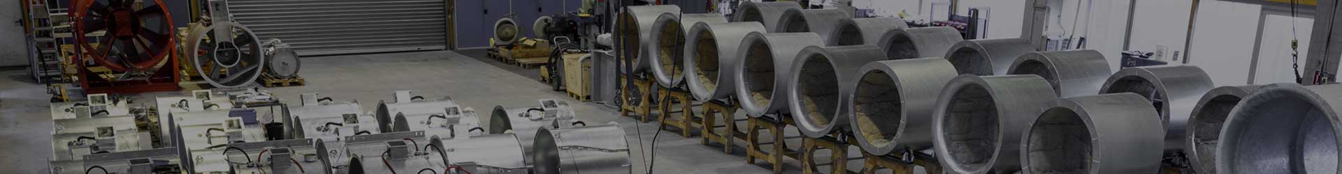
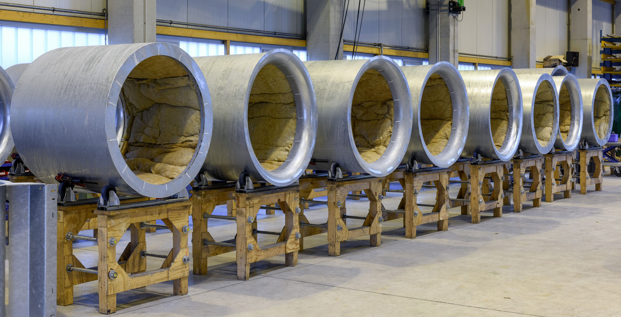
Cylindrical Silencers
As a standard we offer 4 types of cylindrical silencers.
Two types with a pod, CPA-1D and CPA-2D and two types without a pod, CA-1D and CA-2D.
The "D" denominates the nominal length and the internal diameter of the silencers (the 2D silencers have length of double the diameter). Other dimensions are manufactured can also be accommodated. The insertion losses for other dimensions can be found by interpolating the tables.
Rectangular Attenuators
As a standard we offer 7 different modules of rectangular attenuators. The width of a module is varied between 250 mm and 400 mm and the length from 600 to 2400 mm. The modules are varied by the relationship between the silencer wall and the channel to achieve a continues range of insertion loss values. A complete attenuator consist of a number of the same modules combined to match the desired flow rate and duct size.
Sound Enclosures
The sound reduction properties of a sound enclosures is mainly determined by it's design and assembly. A major factor is the material selection and the relative size of the air gaps between the panels.
To cover most applications we have three different sound enclosure types:
1. Sound insulation
The fan casing is clad with sound absorbing material. In most cases inlet/outlet silencers or heavy gadget ducting is required to achieve the desired effect.
2. Sound enclosure type A
Self-supporting baffles are connected with quick-release fasteners and can be completely assembled/disassembled on site. A variety of designs can be realized, e.g. with free intake, duct connection on both sides or with forced ventilation.
3. Sound enclosure type B
As is the case with type B many different designs can be accommodated. The main difference is a supporting frame to provide additional rigidity and heavier gadget material. This type is more suitable for larger installations or installation outside and with type A higher noise insulation is achieved than.
In addition for special applications we offer enclosures with higher insertion losses, for example double walled enclosures.
Expected Insertion Loss Values acc. to VDI 2711:
| Type | Description |
|---|---|
| I. | Sound Insolation |
| IIa−IIc | Normal sound enclosure with reduced air gaps |
| IIIa-IIIb | Double walled enclosures with very reduced air gaps |
Sound absorption coefficients
The values given for the individual silencer types are approximate values which may have significant deviations due to flow turbulence or larger than expected gaps. A tolerance must therefore always be expected, depending on the application.
Dimension sheets
The dimensions of our standard silencers (cylindrical and rectangular silencers) can be found at the end. Principle diagrams of the type A and B sound enclosures are also shown.
Apart from the shown types and dimensions we also manufacture a large number of customized silencers. Please inquire of the need arises.
Selection
The selection of a silencer can best be demonstrated by using an example. The method can be used irrespective of whether a cylindrical silencer, rectangular silencer or an enclosure needs to be dimensioned.
Example
Specification
A discharge attenuator is required to reduce fan noise to 85 dB(A) at 1 metre.
The Oktavband values of the fan are*:
| Description | ||||||||
|---|---|---|---|---|---|---|---|---|
| Oktave band Hz | 64 | 125 | 250 | 500 | 1k | 2k | 4k | 8k |
| Sound power level | 108 | 108 | 109 | 115 | 106 | 105 | 100 | 95 |
Volume flow rate is 0,97 m3/s
Maximum pressure loss through attenuator to be 125 Pa (N/m2)
*From Sound calculation, e. g. from Witt & Sohn Fan Selection Program
Step 1
Determine the attenuator insertion loss from SWL and target noise level
| Description | ||||||||||
|---|---|---|---|---|---|---|---|---|---|---|
| Oktave band | Hz | 63 | 128 | 250 | 500 | 1k | 2k | 4k | 8k | |
| Fan sound pressure level | dB | 108 | 108 | 109 | 115 | 106 | 105 | 100 | 95 | (1) |
| A-Rating | dB | -26 | -16 | -9 | -3 | 0 | +1 | +1 | -1 | (2) |
| Sound pressure in 1m | dB | -8 | -8 | -8 | -8 | -8 | -8 | -8 | -8 | *(3) |
| Target 85 dB (a) | dB | -80 | -80 | -80 | -80 | -80 | -80 | -80 | -80 | **(4) |
| Approx. insertion loss of the damper | dB | - | 4 | 12 | 24 | 18 | 18 | 13 | 6 | (1)+(2+3+4) |
*Assumes free field conditions (no reflections from the wall) over a hemisphere
**As a guideline: 5 dB less than the target noise level in each oktavband
Step 2
Select attenuator to achieve the required insertion loss
| Description | |||||||||
|---|---|---|---|---|---|---|---|---|---|
| Oktave band | Hz | 64 | 125 | 250 | 500 | 1k | 2k | 4k | 8k |
| Required insulation | dB | - | 4 | 12 | 24 | 18 | 18 | 13 | 6 |
| Insertion loss of type 364 | dB | 5 | 8 | 16 | 24 | 29 | 26 | 18 | 16 |
Step 3
Checking that the attenuator insertion loss meets the target noise level
| Description | |||||||||
|---|---|---|---|---|---|---|---|---|---|
| Oktave band | Hz | 64 | 125 | 250 | 500 | 1k | 2k | 4k | 8k |
| Fan sound pressure level | dB | 108 | 108 | 109 | 115 | 106 | 105 | 100 | 95 |
| A-Rating | dB | -26 | -16 | -9 | -3 | 0 | +1 | +1 | -1 |
| Sound pressure in 1m | dB | -8 | -8 | -8 | -8 | -8 | -8 | -8 | -8 |
| Insertion insulation | dB | -5 | -8 | -16 | -24 | -29 | -26 | -18 | -16 |
| A-weighted sound pressure 1m | dB | 69 | 76 | 76 | 80 | 69 | 72 | 75 | 70 |
Total sound level 84 dB(A) according to the normal addition of sound values
Step 4
Determine attenuator cross section to meet the pressure loss requirement
A maximum of 125 Pa pressure loss was specified. The 'K' factor from attenuator insertion loss tabe − for 364 it is 5.9. From the rectangular attenuator pressure loss graph follow the diagonal 'K' factor line equivalent to 5.9 till it meets the 125 N/m2 (horizontal) pressure drop line. From this point go vertically down the graph to the attenuator face velocity in m/sec. In this example, 5.8 m/sec. An attenuator cross section can now be calculated from the required face velocity of 5.8 m/sec and the air volume at 0,97 m3/sec. The (minimum) cross-sectional area in this example is therfore 0,97/58%nbsp;m2 = 0,167 m2.
For a cylindrical attenuator this can be seen directly for the graphs for CPA-1/CPA-2D below.